


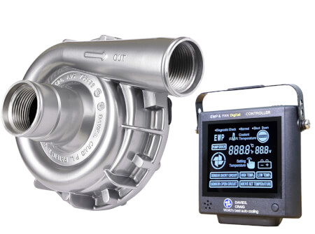
EWP115 ALLOY COMBO ELECTRIC WATER PUMP & CONTROLLER (12V)
EWP®115 Alloy Combo Remote Electric Water Pump & Controller (12V) (Part #8950)
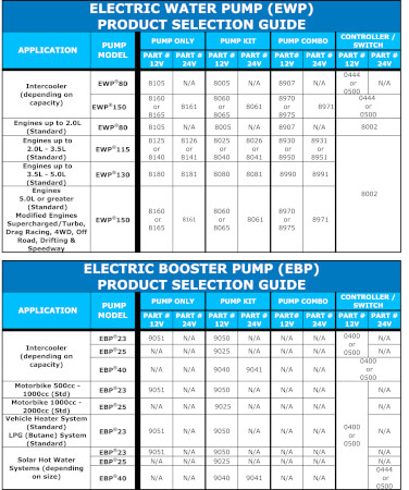
The EWP®115 Alloy 12V is available for purchase in following options:
- Pump Only (Part #8140)
- Kit (Part #8040)
- Combo with Controller (Part #8950)
Take total control of your engine cooling with the Davies Craig EWP®115 Alloy Electric Water Pump and LCD EWP®/Fan Digital Controller. The Controller will also manage the operation of your Thermatic® Fan.
The EWP®115 pump is suitable for small, medium, large, high-performance and 4WD vehicles. It improves engine cooling control and capacity whilst giving you more power and torque and improved fuel economy. Our EWP range are also extensively used in Intercooler Applications.
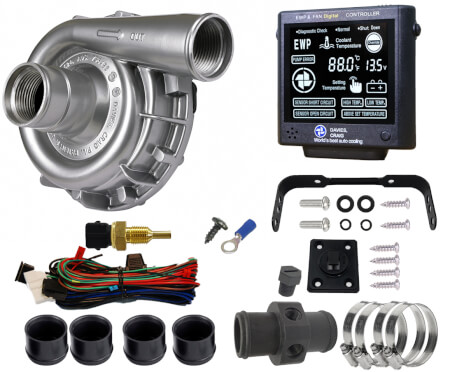
COMBO CONTENTS
PART DESCRPTION | UNITS
EWP®115 Alloy | 1
EWP®/Fan Digital Controller & Mounting Plate + Bracket | 1
Sensor Thermal - coolant temp - ¼" NPT thread | 1
Adaptor - Nylon - In Line, 38mm (2 x 1/4" NPT) | 1
1/4" NPT Nylon - Bung | 1
Wiring Harness | 1
Hose Clamps | 4
SCREW - SELF TAP 8X3/8 BZ | 1
BLUE 6mm Ring Terminal | 1
TECHNICAL SPECIFICATIONS
EWP115 Alloy ELECTRIC WATER PUMP | | LCD Controller
Operating voltage | 3V DC to 15V DC | Voltage range | 12V DC to 29V DC
Maximum current | 10A @ 13V | Display LCD size | 64.6mm (2.54”) x 55.6mm (2.19”)
Flow rate (max) | 139 L/min (36.7 US gal/min) @ 13V DC | Maximum current | 12Amps
Operating temp. | -40° to 120°C (-40° to 248°F) | Warning alarm | High & low Temp., Above set temp., Sensor short circuit, Pump error, High & low voltage and Sensor open circuit
Pump design | Clockwise centrifugal with volute chamber | Targeted (set) temperatures | Singular degrees from:
40°C (104°F)to 110°C (230°F)
Pump weight | 920 grams (2.3 lb) | Memory | Set & targeted temperature
Pump material | Aluminium (Powder Coated) | Fan cut-in temp. | 3°C (5.4°F) above the targeted (set) temperature
Burst pressure | 500 kPa (72.5 psi) | Controller type | PCB with micro-processor
Seal | Ceramic face seal | Sensor type
| Thermister in housing
Self Priming | No, none of our pumps are self-priming
Fits hose sizes&Internal Fitting | 35mm to 51mm (1.38” to 2”) -Inlet & Outlet: -16AN ORB | Overrun/ shutdown | -10°C (14°F) below set/target temperature or 3 minutes
Indicators | Temperature, power, EWP, test, fan, high & low temp, voltage, above set temperature (with alarm)
Push-On fitting Size | EWP Inlet & Outlet 38mmwith 3mm Sleeve (#8510) 44mm with 6mm Sleeve (#8511) 51mm | Weight | 100 grams (3.5 oz)
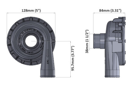
Dimensions | Length = 98mm (3.8")
Width = 95mm (3.7")
Depth = 25mm (1”)
EWP115 Alloy ELECTRIC WATER PUMP | | LCD Controller
Operating voltage | 3V DC to 15V DC | Voltage range | 12V DC to 29V DC
Maximum current | 10A @ 13V | Display LCD size | 64.6mm (2.54”) x 55.6mm (2.19”)
Flow rate (max) | 139 L/min (36.7 US gal/min) @ 13V DC | Maximum current | 12Amps
Operating temp. | -40° to 120°C (-40° to 248°F) | Warning alarm | High & low Temp., Above set temp., Sensor short circuit, Pump error, High & low voltage and Sensor open circuit
Pump design | Clockwise centrifugal with volute chamber | Targeted (set) temperatures | Singular degrees from:
40°C (104°F)to 110°C (230°F)
Pump weight | 920 grams (2.3 lb) | Memory | Set & targeted temperature
Pump material | Aluminium (Powder Coated) | Fan cut-in temp. | 3°C (5.4°F) above the targeted (set) temperature
Burst pressure | 500 kPa (72.5 psi) | Controller type | PCB with micro-processor
Seal | Ceramic face seal | Sensor type
| Thermister in housing
Self Priming | No, none of our pumps are self-priming
Fits hose sizes&Internal Fitting | 35mm to 51mm (1.38” to 2”) -Inlet & Outlet: -16AN ORB | Overrun/ shutdown | -10°C (14°F) below set/target temperature or 3 minutes
Indicators | Temperature, power, EWP, test, fan, high & low temp, voltage, above set temperature (with alarm)
Push-On fitting Size | EWP Inlet & Outlet 38mmwith 3mm Sleeve (#8510) 44mm with 6mm Sleeve (#8511) 51mm | Weight | 100 grams (3.5 oz)
Dimensions | Length = 98mm (3.8")
Width = 95mm (3.7")
Depth = 25mm (1”)
Combined with an LCD EWP®/Fan Digital Controller (Sold separately Part #8002 or EWP® Combo Pack) will manage both the EWP® and Thermatic® fan operation. The Digital Controller will vary the speed of the EWP® in response to the engine’s coolant temperature. Multiple temperature settings are provided on the Controller for either maximum power or fuel efficiency. The Thermatic® Fan/s will be activated automatically once the engine coolant rises 3°C (5.4°F) above the targeted (set) temperature. The Digital Controller will automatically run on for three minutes (or to 10°C / 14°F below the set temperature) after engine shut down, eliminating ‘heat soak’ and extending engine life. The EWP® Controller Combo Pack is supplied in a do-it-yourself kit with everything you need for fitment to your vehicle’s engine, including an easy-to-follow DIY instruction booklet.
The world’s most advanced total engine cooling management system:
universal fit
more power
more cooling
increase fuel efficiency
extend engine life
world-leading technology
EWP® INSTALLATION OPTIONS
Installing an EWP® as an AUXILIARY PUMP
- Leaving the mechanical water pump in place, install the EWP® into the bottom radiator hose.
- Remove the thermostat and drill two approx. 3mm (1/8") holes in the thermostat plate to allow some coolant circulation when the thermostat is closed. Re-install ensuring that the thermostat housing is clean and a new gasket is used if required.
EWP® INSTALLATION – disabling Mechanical water pump
- Leaving the mechanical water pump in place, install the EWP® into the bottom radiator hose and remove the manufacturer’s thermostat.
- You will need to bypass the water pump pulley by installing an appropriate length belt (not supplied). This method makes for an easy installation.
- If running the pump continuously remove the thermostat and drill two approx. 3mm (1/8") holes in the thermostat plate to allow some coolant circulation. Re-install ensuring that the thermostat housing is clean and a new gasket is used if required.
In both these cases, the EWP® will pump past the impeller of the mechanical water pump.
Disengaged mechanical water pump (recommended)
- Remove the mechanical water pump and remove the thermostat.
- Then remove the impeller from the mechanical pump shaft. Retain the mechanical water pump using the pump pulley as an idler to avoid re-routing the drive belt.
- Block any bypass passages and re-install the disengaged water pump ensuring that all gasket surfaces are clean and the new gaskets are properly fitted to prevent leaks.
- Install the EWPÒ into the bottom radiator hose.
Removed mechanical water pump (Ideal)
- Remove the mechanical water pump and thermostat from the engine.
- Install a Davies Craig EWP® Header Adaptor or blanking plate (not supplied). Ensuring the gasket surfaces are clean and the appropriate gasket or sealant is used to prevent leaks.
- Install the EWP® into the bottom radiator hose. This method will require you to modify or replace the standard radiator hose.
- Install an appropriate length belt (not supplied) to drive the accessories.
In most cases EWP® will be adequately supported by the radiator hose. Where mounting is required, the EWP® must be soft mounted to protect against vibration. For the EWP®115, EWP®140 and EWP®150 Part #8700 or #8710 Mounting bracket is recommended.