


EWP80 COMBO REMOTE ELECTRIC WATER PUMP & CONTROLLER (12V)
EWP®80 Combo Remote Electric Water Pump & Controller (12V) (Part #8907)
The EWP®80 is available for purchase in following options:
- Pump Only (Part #8105)
- Kit (Part #8005)
- Combo with Controller (Part #8907)
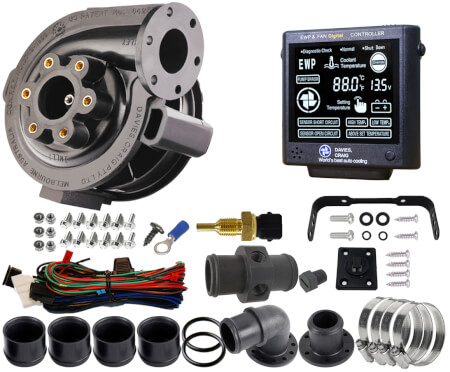
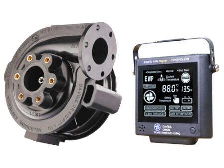
The EWP®80 Electric Water Pump and LCD EWP®/Fan Digital Controller Combo – simple, do-it-yourself, easy to install, designed to complement or replace your existing belt-driven, mechanical water pump and engine thermostat, and operate your Thermatic® Fan.
The EWP®80 will fit most vehicle makes and models fitted with naturally-aspirated or turbo engines up to two litres, 12 Volt Only.
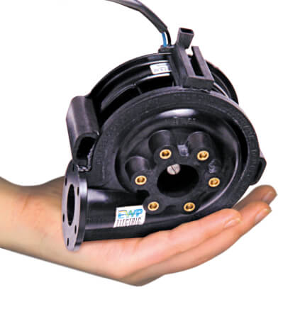
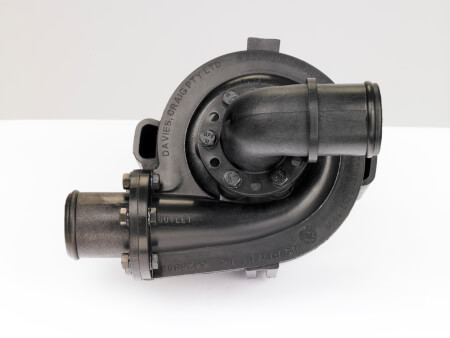
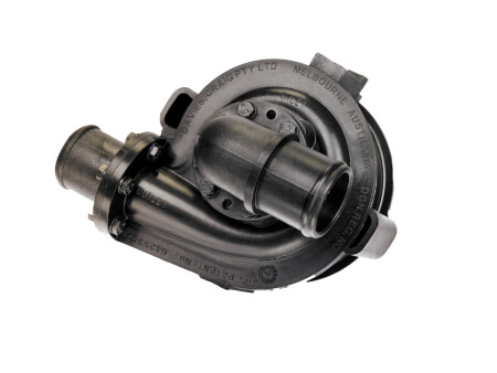
The revolutionary, Australian-designed EWP®80 is made from anti-corrosive, lightweight, heat-resistant, glass-filled nylon and incorporates a ceramic faced seal for long-life durability.
The EWP®80 greatly enhances engine cooling control while giving you added power and improved fuel economy. By removing the parasitic power losses of a belt-driven, mechanical water pump the EWP® can provide up to 10kW (13hp) of extra power and increased torque and used extensively in Intercooler applications.
COMBO CONTENTS
PART DESCRPTION | UNITS
EWP®80 - Nylon 12V Assembly | 1
Nylon Flange Adapter: 35mm Straight | 1
Nylon Flange Adapter: 35mm 90° Elbow | 1
Adapter - Rubber Sleeve - 3mm {1/8"} | 4
HOSE CLAMP (WD9 40-60 W2) EWP (1110020130) | 4
EWP ADAPTER O-RING | 2
Wiring Harness - EWP & Fan controller : suits 8020, 8000, 8001 & 8002 | 1
EWP®/Fan Digital controller | 1
Adaptor - Nylon - In Line, 35mm (2 x 1/4" NPT) | 1
1/4" NPT Nylon - Bung | 1
U-Bracket - For #8002 | 1
Mounting Plate - For #8002 | 1
SCREW - SELF TAP 8X3/8 BZ | 1
BLUE 6mm Ring Terminal | 1
5x12 Flanged Hex Set Screw Zinc Silver | 6
5x16 Flanged Hex Set Screw Zinc Silver/ | 6
M5 FLANGE NUT ZINC SILVER | 6
Sensor Thermal - coolant temp - ¼" NPT thread | 1
TECHNICAL SPECIFICATIONS
EWP®80 - ELECTRIC WATER PUMP |
Operating voltage | 3V DC to 15V DC |
Maximum current | 7.5A @ 13V |
Flow rate (max) | 90 L/min (23.8 US gal/min) @ 13V DC | Maximum current | 12Amps
Operating temp. | -40° to 120°C (-40° to 248°F) |
Warning alarm | High & low Temp., Above set temp., Sensor short circuit, Pump error, High & low voltage and Sensor open circuit
Pump design | Clockwise centrifugal with volute chamber | Targeted (set) temperatures | Singular degrees from:
40°C (104°F) to 110°C (230°F)
Pump weight | 900 grams (2.0 lb) |
Memory | Set & targeted temperature
Pump material | Nylon 66, 30% glass-filled |
Fan cut-in temp. | 3°C (5.4°F) above the targeted (set) temperature
Burst pressure | 350 kPa (50 psi) |
Controller type | PCB with micro-processor
Seal | Ceramic face seal |
Sensor type | Thermister in housing
Fits hose sizes | 32mm to 51mm (1⅜” to 2”) |
Overrun/ shutdown | -10°C (14°F) below set/target temperature or 3 minutes
Self Priming | No, none of our pumps are self-priming | Indicators | Temperature, power, EWP, test, fan, high & low temp, voltage, above set temperature (with alarm)
Weight | 100 grams (3.5 oz)
Dimensions | Length = 98mm (3.8")Width = 95mm (3.7")Depth = 25mm (1”)
Combined with an LCD EWP®/Fan Digital Controller (Sold separately Part #8002 or EWP® Combo Pack) will manage both the EWP® and Thermatic® fan operation. The Digital Controller will vary the speed of the EWP® in response to the engine’s coolant temperature. Multiple temperature settings are provided on the Controller for either maximum power or fuel efficiency. The Thermatic® Fan/s will be activated automatically once the engine coolant rises 3°C (5.4°F) above the targeted (set) temperature. The Digital Controller will automatically run on for three minutes (or to 10°C / 14°F below the set temperature) after engine shut down, eliminating ‘heat soak’ and extending engine life. The EWP® Controller Combo Pack is supplied in a do-it-yourself kit with everything you need for fitment to your vehicle’s engine, including an easy-to-follow DIY instruction booklet.
The world’s most advanced total engine cooling management system:
universal fit
more power
more cooling
increase fuel efficiency
extend engine life
world-leading technology
EWP® INSTALLATION OPTIONS
Installing an EWP® as an AUXILIARY PUMP
- Leaving the mechanical water pump in place, install the EWP® into the bottom radiator hose.
- Remove the thermostat and drill two approx. 3mm (1/8") holes in the thermostat plate to allow some coolant circulation when the thermostat is closed. Re-install ensuring that the thermostat housing is clean and a new gasket is used if required.
EWP® INSTALLATION – disabling Mechanical water pump
- Leaving the mechanical water pump in place, install the EWP® into the bottom radiator hose and remove the manufacturer’s thermostat.
- You will need to bypass the water pump pulley by installing an appropriate length belt (not supplied). This method makes for an easy installation.
- If running the pump continuously remove the thermostat and drill two approx. 3mm (1/8") holes in the thermostat plate to allow some coolant circulation. Re-install ensuring that the thermostat housing is clean and a new gasket is used if required.
In both these cases, the EWP® will pump past the impeller of the mechanical water pump.
Disengaged mechanical water pump (recommended)
- Remove the mechanical water pump and remove the thermostat.
- Then remove the impeller from the mechanical pump shaft. Retain the mechanical water pump using the pump pulley as an idler to avoid re-routing the drive belt.
- Block any bypass passages and re-install the disengaged water pump ensuring that all gasket surfaces are clean and the new gaskets are properly fitted to prevent leaks.
- Install the EWPÒ into the bottom radiator hose.
Removed mechanical water pump (Ideal)
- Remove the mechanical water pump and thermostat from the engine.
- Install a Davies Craig EWP® Header Adaptor or blanking plate (not supplied). Ensuring the gasket surfaces are clean and the appropriate gasket or sealant is used to prevent leaks.
- Install the EWP® into the bottom radiator hose. This method will require you to modify or replace the standard radiator hose.
- Install an appropriate length belt (not supplied) to drive the accessories.
In most cases EWP® will be adequately supported by the radiator hose. Where mounting is required, the EWP® must be soft mounted to protect against vibration. For the EWP®115, EWP®140 and EWP®150 Part #8700 or #8710 Mounting bracket is recommended.